STANDARDS AUSTRALIA Australian Standard Scaffold Planks
View this page in pdf format (download/print)SECTION 1 SCOPE AND GENERAL
1.1 SCOPE This Standard specifies requirements for the design, manufacture and performance of scaffold planks.
The Standard does not apply to prefabricated platforms (see AS 1576.3).
NOTE: Alternative methods for determining compliance with this Standard are given in Appendix E.
1.2 APPLICATION The performance of scaffold planks shall comply with Section 2, and the manufacture shall comply with Sections 3, 4 and 5 as follows:
(a) Solid timber scaffold planks . . . . . . . . . . . . . . . . . Section 3.
(b) Vertically laminated timber scaffold planks . . . . . Section 4.
(c) Metal scaffold planks . . . . . . . . . . . . . . …… . Section 5.
1.3 REFERENCED DOCUMENTS
The following documents are referred to in this Standard: AS…
[table id=42 /]1.4 USE OF ALTERNATIVE MATERIALS OR METHODS: This Standard does not preclude the use of methods or materials other than those specified, provided that such new methods or materials can be proved, by appropriate performance testing, to be equal to or better than those described herein. Service durability shall be a consideration in assessing the new methods or materials
1.5 DEFINITIONS: For the purpose of this Standard, the definitions given in AS O1, and those below apply.
1.5.1 Bow—a curvature from the plane of the wide face in the direction of length (see Figure 1(a)).
1.5.2 Captive plank—a scaffold plank which is designed and intended to be contained and supported by purpose-designed transoms in such a way as to preclude the possibility of uplift.
1.5.3 Cup—a concave warping in the width direction of the plank (see Figure 1(b)).
1.5.4 Random plank—a scaffold plank of any length which is designed and intended to be simply supported by putlogs and to overhang its end supports.
1.5.5 Scaffold plank—a decking component, other than a prefabricated platform, which is used or intended to be used in the construction of any platform supported by scaffolding.
1.5.6 Sliding—the movement of a plank relative to its supports.
1.5.7 Slip—the movement of an object or person on the surface of the plank.
1.5.8 Spring—a longitudinal curvature of the edge of a plank not affecting the face (see Figure 1(c)).
1.5.9 Twist—a spiral distortion along the length of a piece of plank (see Figure 1(d)).
1.5.10 Uplift—the lifting of one end of a plank when a downward force is applied to the other end of the plank.
1.5.11 Working load limit—the maximum allowable working load on the scaffold plank during use.
FIGURE 1 BOW, CUP, SPRING, TWIST:

1.6 WIDTH OF PLANKS
1.6.1 Minimum width: The minimum width of a scaffold plank shall be 220 mm. For timber planks, the minimum width shall be at a moisture content not exceeding 15 percent. The moisture content shall be measured in accordance with AS 1080.1.
1.6.2 Tolerance on width: The tolerance on the width of a scaffold plank shall be −0, +5mm.
1.7 MANUFACTURING TOLERANCES: Except for solid timber scaffold plank which shall comply with Clause 3.6.2, bow and spring shall not exceed 2 mm per metre length of plank. Twist, when measured on the top surface along the edge of the working surfaces, shall not exceed 2 mm per metre length of plank, to a maximum of 8 mm.
1.8 WORKING LOAD LIMIT: When supported at the nominated maximum design span, the working load limit in kilonewtons at the midpoint between supports shall be not less than 2b/220, where b is plank width in millimetres.
1.9 PRINCIPLES OF DESIGN: The design of a scaffold plank shall take into account the following:
(a) The range of environmental conditions and applications in which the scaffold plank is likely to be used.
(b) The handling normally associated with scaffolding.
(c) The safety of persons engaged in the erection, alteration and dismantling of the range of scaffolds for which the scaffold plank is intended to be used.
(d) The safety of persons using the range of scaffolds for which the scaffold plank is intended.
(e) The safety of persons in the vicinity of the range of scaffolds for which the scaffold plank is intended.
1.10 INFORMATION FROM SUPPLIER: The supplier shall provide the following documented information:
(a) Instructions for transportation, storage and maintenance.
(b) Guidance on the range of scaffolds for which the plank is suitable.
(c) In the case of random planks, the manufacturer’s recommended maximum span between supports and overhang.
(d) The nominal weight of the plank.
NOTE: The weight may be critical in relation to dislodgment due to the effect of wind.
(e) The recommended method of securing the scaffold plank against dislodgment or uplift, if applicable.
(f) Criteria for rejection or reworking.
1.11 MARKING: Each scaffold plank shall be permanently and legibly marked with the following:
(a) Manufacturer’s name or identification.
(b) The number of this Australian Standard, i.e. AS 1577.
(c) Working load limit, in kilograms.
(d) For random planks, the allowable span, in metres. The marking shall be in a manner to survive the expected life of the plank. In addition, solid timber scaffold planks shall be branded on an edge with a letter to denote whether it is visually graded (V), or machine-graded (M). For solid timber planks, the lettering used shall be not less than 25 mm high and the brands shall be spaced not more than 1.8 m apart.
NOTE: Manufacturers making a statement of compliance with this Australian Standard on a product, packaging, or promotional material related to that product are advised to ensure that such compliance is capable of being verified.
SECTION 2 PERFORMANCE REQUIREMENTS
2.1 GENERAL: The performance of a scaffold plank shall be verified by testing.
2.2 TESTING:
2.2.1 Stiffness test: When tested in accordance with Appendix A, the deflection of the plank shall not exceed span/100, to a maximum of 25 mm.
2.2.2 Strength test: When tested in accordance with Appendix B, planks shall comply with the following requirements:
(a) When tested to Paragraph B4(a) to (e), planks shall not show visual signs of distress, buckling or permanent deformation exceeding span/500. In addition timber planks shall not show audible signs of distress.
(b) When tested to Paragraph B4(f) and (g), the failure load shall be not less than 1.1 Ft , where Ft is the test load, in kilonewtons.
(c) The mode of failure shall be to fail progressively and not break into separate parts.
2.2.3 Sliding test: When tested in accordance with Appendix C, the force required to produce sliding shall be not less than 250 N.
2.2.4 Slip test: When tested in accordance with Appendix D, the plank surface shall have a static coefficient of friction of not less than 0.7.
SECTION 3 SOLID TIMBER PLANKS
3.1 SCOPE OF SECTION This Section specifies manufacturing requirements for one-piece softwood and hardwood solid timber planks.
3.2 TIMBER SPECIES Hardwood and softwood timber species shall be strength group 6 or better, in accordance with AS 2878.
NOTE: Refer to Appendix F for hardwood and softwood timber species.
3.3 MOISTURE CONTENT
3.3.1 Softwoods Softwood planks shall be seasoned, i.e. the moisture content of the plank shall not exceed 15 percent, when measured in accordance with AS 1080.1.
3.3.2 Hardwoods Hardwood planks of strength groups SD5 and SD6, in accordance with AS 2878, shall be seasoned, i.e. the moisture content of the plank shall not exceed 15 percent, when measured in accordance with AS 1080.1. Hardwood planks of strength groups S1 to S4, in accordance with AS 2878, may be seasoned or unseasoned.
3.4 SURFACE FINISH The planks shall have a face finished surface with roughness not less than a sawn finish, and a sawn or dressed finished surface on the edges. The surface shall not be treated with paint or other material which would obscure the grain, except that colour identification bands not exceeding 100 mm wide may be painted on at positions commencing not less than 300 mm from the ends of the plank.
3.5 THICKNESS OF PLANK
3.5.1 Minimum thickness
3.5.1.1 Softwoods The minimum thickness of a softwood plank, at a moisture content not exceeding 15 percent, shall be 38 mm.
NOTE: If a scaffold plank has less than 15 percent moisture content, the thickness may be less than 38 mm by an amount equivalent to the shrinkage occurring due to drying to a lower moisture content.
3.5.1.2 Hardwoods The minimum thickness of a hardwood plank at a moisture content not exceeding 15 percent shall be 38 mm for seasoned hardwoods of strength groups SD5 and SD6 and 32 mm for seasoned hardwoods of strength groups SD1 to SD4 and unseasoned hardwoods of strength groups S1 to S4.
NOTE: If a scaffold plank is less than 15 percent moisture content, the thickness may be less than those set down in this Clause by an amount equivalent to the shrinkage occurring due to drying to a lower moisture content.
3.5.2 Tolerance on thickness The tolerance on the thickness shall be −0, +3 mm.
3.6 GRADING
3.6.1 General Solid timber planks shall be visually or mechanically graded.
3.6.2 Visual grading
3.6.2.1 Softwoods Visually graded softwood planks shall be of sound wood showing not less than four growth rings per 25 mm and shall be truly sawn. The timber shall be free from compression failure, loose or encased knots and holes exceeding 20 mm diameter, and pith. The following imperfections shall be permitted:
(a) Knots, sound and intergrown—not exceeding one-sixth the width of the surface on which they occur, and provided knots of maximum permissible size are spaced not less than 450 mm apart. Groups of small knots shall be permitted, provided the aggregate width of the group in any 450 mm length of plank does not exceed 50 mm
(b) Slope of grain —not exceeding 1 in 12 when measured over a distance of not less than 300 mm.
(c) Bow and spring—bow not exceeding 1 mm per 300 mm length of plank, and spring not exceeding 1 mm per 600 mm length of plank.
(d) Twist—not exceeding 1 mm per 600 mm length of plank, to a maximum of 8 mm.
(e) End splits —not exceeding 150 mm individually and not more than 200 mm in total at each end.
(f) Check s —not exceeding 300 mm long and 3 mm wide.
(g) Resin and bark pockets— not exceeding 300 mm long and 3 mm wide.
(h) Resin streaks—unlimited.
(i) Want or wane—not exceeding (width + thickness)/20, in millimetres, on any one edge or face.
3.6.2.2 Hardwoods Visually graded hardwood planks shall be of sound wood, and be truly sawn. The timber shall be free from defective heart, compression failure, pin holes, loose knots and holes exceeding 20 mm diameter, grub holes and borer holes, gum pockets and decay. The following imperfections shall be permitted:
(a) Knots, sound and intergrown—not exceeding one-sixth the width of the surface on which they occur, and provided knots of maximum permissible size are spaced not less than 450 mm apart.
(b) Slope of grain—not exceeding 1 in 16 when measured over a distance of not less than 300 mm.
(c) Bow and spring— not exceeding 16 mm in length of the plank.
(d) Twist— not exceeding 1 mm per 600 mm length of plank to a maximum of 8 mm.
(e) End splits—not exceeding 150 mm individually, and not more than 200 mm in total at each end.
(f) Checks— not exceeding 300 mm long and 3 mm wide.
(g) Tight gum veins—not extending from face to face, and aggregate length not exceeding the length of the piece.
(h) W ant or wane—not exceeding (width + thickness)/20, in millimetres, on any one edge or face.
(i) Sapwood—
(i) Non-susceptible to Lyctus borer—unlimited.
(ii) Susceptible to Lyctus borer—provided the sapwood and wane combined does not exceed (width + thickness)/20, in millimetres.
(iii) If treated with a non-leachable preservative to Hazard 1 of AS 1604—unlimited.
3.6.3 Mechanical grading
3.6.3.1 General This Clause specifies the moduli of elasticity and the visual grading requirements for mechanically graded softwoods and hardwood solid timber scaffold planks to ensure performance comparable with that anticipated from planks visually graded in accordance with Clause 3.6.2.
3.6.3.2 Grading m achine The mechanical grading machine and the operation shall be in accordance with AS 1748 and AS 1749.
3.6.3.3 Stiffness requirem ent Softwoods and seasoned hardwood planks of strength groups SD5 and SD6, when tested throughout their length over spans of 900 mm, shall have a minimum modulus of elasticity of not less than 7600 MPa.
Seasoned or unseasoned hardwood planks of strength groups S1 to S4, when tested throughout their length over spans of 900 mm, shall have a minimum modulus of elasticity not less than 9700 MPa
3.6.3.4 Grading of ends As the end sections of planks cannot be effectively machine graded, they shall be inspected to ensure that no imperfection, or combination of imperfections, of worse appearance than permitted elsewhere in the plank is present.
3.6.3.5 Visual inspection All mechanically graded planks, in addition to complying with all the appropriate requirements of this Clause shall meet the following requirements:
(a) Seasoned softwoods— all the requirements of Clause 3.6.2.1 except Clause 3.6.2.1(a).
(b) Seasoned hardwoods of strength groups SD5 and SD6—all the requirements of Clause 3.6.2.2 except Clause 3.6.2.2(a) and 3.6.2.2(b). The slope of grain shall not exceed 1 in 12 when measured over a distance of not less than 300 mm.
(c) Seasoned hardwoods of strength groups SD1 to SD4—all the requirements of Clause 3.6.2.2 except Clauses 3.6.2.2(a) and 3.6.2.2(b). The slope of grain shall not exceed 1 in 12 when measured over a distance of not less than 300 mm.
(d) Unseasoned hardwoods of strength groups S1 to S4—all the requirements of Clause 3.6.2.2 except Clause 3.6.2.2(a).
3.7 COMBINATION OF IMPERFECTIONS Imperfections permitted in Clause 3.6.2.1 or Clause 3.6.2.2 shall be permitted in combination, provided the cumulative effect of the combination, as assessed by visual grading, does not exceed the effect of a single imperfection of the maximum permissible size. In cases of doubt as to the cumulative effect of a combination of imperfections, the strength test in Clause 2.2.2 shall be applied to the plank. If the plank meets the
performance requirements and passes the visual inspection requirements for mechanically stress-graded planks (see Clause 3.6.3), it shall be accepted.
3.8 END TREATMENT The ends of each solid timber scaffold plank shall have a metal, timber or plastic piece securely fixed to the plank to restrain end splitting.
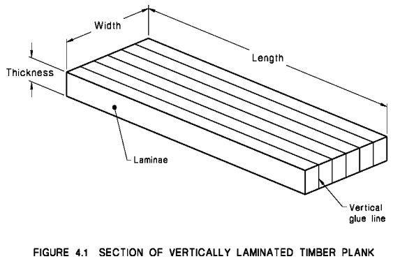
SECTION 4 VERTICALLY LAMINATED TIMBER PLANKS
4.1 SCOPE OF SECTION This Section specifies manufacturing requirements for vertically laminated timber scaffold planks.
The laminations in the scaffold plank shall be vertical (see Figure 4.1).
NOTE: Each end of a laminated timber plank may have a device that protects it from end splitting.
4.2 SURFACE FINISH The planks shall have a face finished surface with roughness not less than a sawn finish, and a sawn or dressed finished surface on the edges. The surface shall not be treated with paint or other material which would obscure the grain, except that colour identification bands not exceeding 100 mm wide may be painted on at positions commencing not less than 300 mm from the ends of the planks.
4.3 MATERIALS All timber laminations shall comply with Section 3 of this Standard, except that the following imperfections shall be permitted:
(a) Knots—not exceeding one-half of the width of the surface on which they occur.
(b) Cupping of the lamination surface to be bonded—0.2 mm maximum.
(c) Bow and spring—not exceeding 25 mm in length of lamina.
(d) Twist—not exceeding 6 mm in length of lamina.
(e) Slope of grain—not exceeding 1 in 10.
(f) Width of individual lamination—measured on the face of the plank, not exceeding
38 mm.
4.4 MANUFACTURE
4.4.1 General In any plank, all laminations shall be of the same species. Each lamina shall be the full length of the plank or be end-jointed in accordance with Clauses 4.4.4 or 4.4.5. Laminations shall comply with the requirements of AS 1328.
4.4.2 Surfaces for bonding All surfaces of laminations to be bonded shall be clean, smooth and free from imperfections, irregularities, loosely adhering particles, preservative salts, dust or contamination likely to inhibit close and firm contact. The surfaces for bonding shall be (see AS 1728)—
(a) No. 5 sawn surface (smooth);
(b) No. 3 dressed surface (medium), provided any glazing shall be broken by abrading;
or
(c) No. 1 abraded surface (medium).
4.4.3 Storage time The elapsed time between the preparation of a surface to be bonded and the bringing together and bonding of the surface shall not exceed 72 h, provided that the prepared material shall be stored in a place and manner that will maintain the moisture content of the material at the desired level and ensure that the bond surfaces remain
uncontaminated.
4.4.4 Finger-jointing Finger-joints, when used in laminations, shall be made in clear timber, free from defects within 75 mm of any joint.
4.4.5 Scarf joints Scarf joints shall comply with the following requirements:
(a) No defect shall be permitted within 75 mm of any scarf joint.
(b) The slope of the scarf shall not be steeper than 1 in 10.
(c) When matching scarfs are brought together, the surfaces of the scarfs shall be in contact over the whole area of the scarfs.
4.5 ADHESIVES AND ADHESIVE SPREAD
4.5.1 Adhesives Adhesives used for laminating or end-jointing shall be a resorcinol or phenolic/resorcinol or polyphenolic tannins type complying with AS 1328.
4.5.2 Use of adhesive The mixing time, the maximum and minimum intervals between mixing and spreading, the maximum and minimum assembly periods, the pressure, and the curing conditions shall be in accordance with the recommendations of the adhesive manufacturer.
4.5.3 Age of adhesive No adhesive shall be used after the age limit of the batch from which it came has expired.
4.5.4 Adhesive spread Where the adhesive manufacturer does not specify the adhesive spread for the bonding of the planks, a minimum spread of 23 kg per 100 m2 of bond shall be used.
4.5.5 Bonding of preservative-treated laminations Where the laminations to be bonded have been preservative treated they shall comply with AS 1328.
4.6 ASSEMBLY Joints and laminations shall be assembled as follows:
(a) Previously end-jointed laminations shall have the surfaces which are to be bonded, machined or remachined before the laminations are bonded together.
(b) Laminations in any one plank may be mixed quartersawn and backsawn, but a fully backsawn lamination shall not be placed next to a fully quartersawn lamination.
(c) The minimum spacing between tips of adjacent joints in adjoining laminations shall be not less than 150 mm.
(d) Each face to be bonded shall be spread with adhesive.
(e) The bonding pressures shall be maintained on the joint for the full time recommended by the adhesive manufacturer.
(f) There shall be no voids in any bond zones in any assembled joint after release of pressure and machining.
(g) The cramping pressures shall be uniform over the whole gluing area, and shall be in accordance with the glue manufacturer’s instructions for the glue used.
(h) The temperature at the time of assembly and during curing of the glueline shall be in accordance with the glue manufacturer’s instructions for the glue used.
4.7 THICKNESS The minimum thickness of laminated timber scaffold planks shall be 35 mm for softwood and hardwood.
SECTION 5 METAL PLANKS
5.1 SCOPE OF SECTION This Section specifies manufacturing requirements for metal planks.
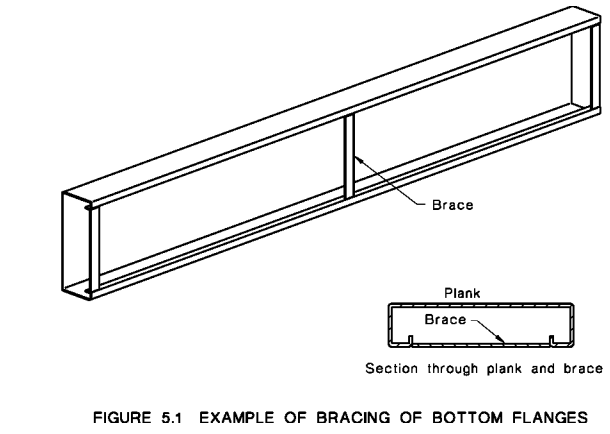
5.2 DESIGN The design of metal planks shall comply with AS 1250, AS 1538 AS 1664 or AS 4100 as appropriate. Welding shall comply with AS 1554 or AS 1665 as appropriate. Planks designed as a channel section, open on the underside, may have the bottom flanges braced by connecting metal straps to prevent the flanges buckling under load (see Figure 5.1). These straps shall be of sufficient strength not to be damaged or dislodged by normal usage.
5.3 MATERIALS
5.3.1 Aluminium
5.3.1.1 Cast com ponents Components shall be designed to enable the scaffold plank to comply with Section 2 of this Standard. They shall also comply with AS 1874 and meet the following minimum mechanical properties:
(a) Ultimate tensile strength . . . . . . . . . . . . 160 MPa.
(b) Elongation . . . . . . . . . . . . . . ……. . 3 percent.
Where pressure die-casting is used as a method of manufacture, the casting technique shall ensure compliance with the above properties. The 700 series alloys shall not be used
5.3.1.2 Wrought components Components made from wrought alloys shall comply with AS 1866 for extrusions and AS 1734 for sheet and plate.
5.3.2 Steel Steel shall comply with AS 1397, AS 1444, AS 1594, AS 3678 or AS 3679.1 as appropriate.
5.4 END FINISH The ends of planks shall be finished flush by folding the metal or by fitting end plates, caps or castings. These shall be securely fixed in position by bolting, riveting, welding or swaging and may be made from metal or high-impact plastic. The method of fixing end plates, caps or castings shall be able to withstand normal usage.
5.5 SURFACE FINISH All surfaces shall be free from burrs and sharp edges that could cause injury in normal use or handling. Where the surface of the plank is perforated, such openings shall have a maximum diameter of 13 mm or a maximum area of 135 mm2
.
5.6 CORROSION PROTECTION Planks made from black steel shall be hot-dip galvanized after fabrication, in accordance with AS 1650. Planks made from galvanized or zinc-aluminium-coated sheet that have had attachments welded to them shall be painted with anti-corrosion paint over any weld area.
APPENDIX A: STIFFNESS TEST (NORMATIVE)
A1 SCOPE This Appendix sets out a method for measuring the deflection of scaffold planks in bending, under a specified loading.
A2 PRINCIPLE A scaffold plank is loaded in static bending in a test rig and its deflection is measured.
A3 APPARATUS The following apparatus is required:
(a) Test rig comprising a rigid base with supports which span the full width of the plank being tested, and a method of applying a concentrated load at mid-span. For random planks, the supports shall be 48.3 mm outside diameter tube in accordance
with AS 1576.3 Supplement 1. For captive planks, supports should be those for which the planks are designed.
(b) Measuring equipment capable of reading the applied load with an accuracy of 5 percent.
(c) Measuring equipment capable of reading the deflection with an accuracy of 5 percent.
(d) A circular loading pad of rubber or similar material 100 ±2 mm in diameter and 50 ±2 mm in thickness. The loading pad shall have a shore durometer hardness of 60 ±5.
A4 PROCEDURE The procedure shall be as follows:
(a) The scaffold plank is to be simply supported at the maximum span for which it is intended to be used but not less than 1.0 m. Each end is to be supported across its full load-bearing width.
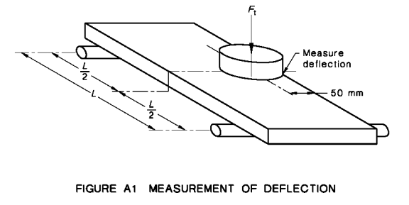
(b) Locate the loading pad at mid-span and the centre of the pad 50 mm in from one side of the plank. Apply a pre-loading of 100 N for 1 min through the circular loading pad. Measure the deflection of the plank under load, at the top surface of the plank nearest the loading point.
(c) The load is to be increased gradually at an even rate to the test loading (Ft), and retained for 15 min. The test loading shall be the working load limit in accordance with Clause 1.8.
(d) Measure the deflection of the plank under load, at the top surface of the plank at the load point (see Figure A1).
A5 CALCULATION The deflection of the scaffold plank shall be calculated as the difference in deflection under pre-loading and the test loading.
A6 REPORT The report shall include the following information:
(a) Scaffold plank material.
(b) Nominal dimensions of scaffold plank.
(c) Identity of manufacturer or supplier.
(d) Detailed and numbered drawing of scaffold plank, where relevant.
(e) The test load applied to the scaffold plank, and the span of the test specimen.
(f) The amount of deflection of the scaffold plank, in millimetres, and whether the scaffold plank passed or failed the test.
(g) Location of testing facility.
(h) Detailed description, drawing or photograph of the test rig.
(i) Date and time of the test.
(j) Names, positions and qualifications of personnel carrying out or supervising the test.
(k) Names, positions and qualifications of witnesses, if any, to the test.
(l) Each page of report to be signed and dated by person responsible for the test.
(m) A reference to this test method, i.e. AS 1577, Appendix A.
APPENDIX B: STRENGTH TEST (NORMATIVE)
B1 SCOPE This Appendix sets out a method for determining the strength of scaffold planks in bending.
B2 PRINCIPLE A scaffold plank is loaded in static bending in a test rig and inspected for failure.
B3 APPARATUS The following apparatus is required:
(a) A test rig comprising a rigid base with supports which span the full width of the plank being tested and a method of applying a concentrated load at mid-span. For random planks, the support shall be 48.3 mm outside diameter tube in accordance with AS 1576.3 Supplement 1. For captive planks, support shall be those for which the planks are designed.
(b) Measuring equipment capable of reading the applied load with an accuracy of 5 percent.
(c) Measuring equipment capable of reading the deflection with an accuracy of 5 percent.
(d) A circular loading pad of rubber or similar material 100 ±2 mm wide and 50 ±2 mm in thickness. The loading pad shall have a shore durometer hardness of 60 ±5.
B4 PROCEDURE The procedure shall be as follows:
(a) The scaffold plank is to be simply supported at the maximum span for which it is intended to be used, but not less than 1.0 m. Each end is to be supported across its full load-bearing width.
(b) Locate the loading pad at mid-span centrally on the plank. Apply a pre-loading of 100 N for 1 min through the loading pad. Measure the deflection of the plank under load, at the underside of the plank.
(c) The load is to be increased gradually at an even rate to the test loading (Ft) and retained for 15 min. The test loading shall be twice the working load limit in Clause 1.8.
(d) Inspect the plank under loading for signs of distress
NOTE: For timber planks, the signs may be visual or audible. For metal planks, the signs may include buckling.
(e) Reduce the test loading to the pre-loading of 100 N, and measure the deflection at the underside of the plank at the centre. Where this measurement exceeds the deflection given in Paragraph B4(b), the difference shall be recorded as permanent deformation.
(f) Resume the application of a gradually increasing load, until the plank fails.
(g) Record the load at failure and the mode of failure.
B5 REPORT The report shall include the following information:
(a) Scaffold plank material.
(b) Nominal dimensions of scaffold plank.
(c) Identity of manufacturer or supplier
(d) Detailed and numbered drawing of scaffold plank, where relevant.
(e) The test load applied to the scaffold plank, and the span of the test specimen.
(f) Signs of distress under load or permanent deformation.
(g) Load at failure and mode of failure.
(h) Whether the scaffold plank passed or failed the test.
(i) Location of testing facility.
(j) Detailed description, drawing or photograph of the test rig.
(k) Date and time of the test.
(l) Names, positions and qualifications of personnel carrying out or supervising the test.
(m) Names, positions and qualifications of witnesses, if any, to the test.
(n) Each page of report to be signed and dated by person responsible for the test.
(o) A reference to this test method, i.e. AS 1577, Appendix B.
APPENDIX C: SLIDING TEST (NORMATIVE)
C1 SCOPE This Appendix sets out a method for determining the resistance to sliding of scaffold planks supported on scaffold tube only. Planks incorporated in capture plank systems are not subject to this test.
C2 PRINCIPLE A scaffold plank is loaded mid-span and then subjected separately, to a longitudinal loading and transverse loading to produce sliding.
C3 APPARATUS A testing machine of adequate capacity capable of measuring loading with an accuracy of 5 percent.
C4 PROCEDURE The procedure shall be as follows:
(a) The scaffold plank is to be simply supported at the maximum span for which it is intended to be used, but not less than 1.0 m. Each end is to be supported across its full load-bearing width on fixed new, or as new, galvanized scaffold tube.
(b) Place a mass of 100 kg on the scaffold plank across the full width of the plank, at mid-span.
(c) Apply a gradually increasing force horizontally at mid-thickness centrally at one end of the plank in a direction longitudinal to its span.
(d) Measure and record the force at which sliding occurs.
(e) Apply a gradually increasing force horizontally at mid-thickness and mid-span of the plank, in a direction transverse to its span.
(f) Measure and record the force at which sliding occurs.
C5 REPORT The report shall include the following information:
(a) Scaffold plank material.
(b) Nominal dimensions of scaffold plank.
(c) Identity of manufacturer or supplier.
(d) Detailed and numbered drawing of scaffold plank, where relevant.
(e) The loading applied to the end of the plank in a direction longitudinal to its axis at which sliding occurs.
(f) The loading applied in a direction transverse to the axis of the plank at which sliding occurs.
(g) Whether the scaffold plank passed or failed the test.
(h) Location of testing facility.
(i) Detailed description, drawing or photograph of the test rig.
(j) Date and time of the test.
(k) Names, positions and qualifications of personnel carrying out or supervising the test.
(l) Names, positions and qualifications of witnesses, if any, to the test.
(m) Each page of report to be signed and dated by person responsible for the test.
(n) A reference to this test method, i.e. AS 1577, Appendix C.
APPENDIX D: SLIP TEST (NORMATIVE)
D1 SCOPE This Appendix sets out a method for determining the slip resistance of the surface of a scaffold plank.
D2 PRINCIPLE A scaffold plank is vertically loaded and this load is subjected to a horizontal force to produce slipping.
D3 APPARATUS The following apparatus is required:
(a) A testing machine of adequate capacity capable of measuring loading with an accuracy of 5 percent.
(b) A smooth rubber pad 300 mm long × 100 mm wide × 6 mm thick with a shore durometer hardness of 60 ±5 attached to the underside of a stiff base, such as an 8 mm thick steel plate or 19 mm thick plywood.
D4 PROCEDURE The procedure shall be as follows:
(a) The scaffold plank is to be supported horizontally and restrained against longitudinal and transverse movement.
(b) Place the rubber pad on the scaffold plank at a location representative of the plank surface. On top of the stiff base and centrally positioned place a 25 kg weight.
(c) Apply a gradually increasing horizontal force to the stiff base, in a direction longitudinal to the plank’s axis.
(d) Measure and record the force at which slip occurs.
D5 CALCULATIONS The coefficient of static friction shall be calculated as follows:
µ = . . . D(1) Fh
Fv
where
µ = coefficient of static friction
Fh = horizontal force to produce sliding, in newtons
Fv = total vertical load of 25 kg weight, stiff base and rubber pad, in newtons
D6 REPORT The report shall include the following information:
(a) Scaffold plank material.
(b) Nominal dimensions of scaffold plank.
(c) Identity of manufacturer or supplier.
(d) Detailed and numbered drawing of scaffold plank, where relevant.
(e) The loading at which slipping occurred.
(f) The coefficient of static friction.
(g) Whether the scaffold plank passed or failed the test.
(h) Location of testing facility.
(i) Detailed description, drawing or photograph of the test rig.
(j) Date and time of the test.
(k) Names, positions and qualifications of personnel carrying out or supervising the test.
(l) Names, positions and qualifications of witnesses, if any, to the test.
(m) Each page of report to be signed and dated by person responsible for the test.
(n) A reference to this test method, i.e. AS 1577, Appendix D.
APPENDIX E: MEANS FOR DEMONSTRATING COMPLIANCE WITH THIS STANDARD (NORMATIVE)
E1 SCOPE This Appendix sets out the following different means by which compliance
with this Standard can be demonstrated by the manufacturer or supplier:
(a) Assessment by means of statistical sampling.
(b) The use of a product certification scheme.
(c) Assurance using the acceptability of the supplier’s quality system.
(d) Other such means proposed by the manufacturer or supplier and acceptable to the
customer.
E2 STATISTICAL SAMPLING Statistical sampling is a procedure which enables decisions to be made about the quality of batches of items after inspecting or testing only a portion of those items. This procedure will only be valid if the sampling plan has been determined on a statistical basis and the following requirements are met:
(a) The sample must be drawn randomly from a population of product of known history. The history must enable verification that the product was made from known materials at essentially the same time by essentially the same processes and under essentially the same system of control.
(b) For each different situation, a suitable sampling plan needs to be defined. A sampling plan for one manufacturer of given capability and product throughput may not be relevant to another manufacturer producing the same items. In order for statistical sampling to be meaningful to the customer, the manufacturer or supplier needs to demonstrate how the above conditions have been satisfied. Sampling and the establishment of a sampling plan should be carried out in accordance with AS 1199, guidance to which is given in AS 1399.
E3 PRODUCT CERTIFICATION The purpose of product certification is to provide independent assurance of the claim by the manufacturer that products comply with the stated Australian or international Standard. The certification scheme should meet the criteria of an ISO Type 5 scheme as specified by SAA HB18.44 in that, as well as full type testing from independently sampled production and subsequent verification of conformance, it requires the manufacturer to maintain an effective quality plan to control production to ensure conformance with the relevant
Standard. The certification scheme serves to indicate that the products consistently conform to the requirements of the Standard.
E4 SUPPLIER’S QUALITY SYSTEM Where the manufacturer or supplier can demonstrate an audited and registered quality management system complying with the requirements of the appropriate or stipulated Australian or international Standard for supplier’s quality systems, this may provide the necessary confidence that the specified requirements will be met. The quality assurance requirements need to be agreed between the customer and supplier and should include a quality or inspection and test plan to ensure product conformity. Guidance in determining the appropriate quality management system is given in AS 3900.1 and AS 3904.1.
E5 OTHER MEANS OF ASSESSMENT If the above methods are considered inappropriate, determination of compliance with the requirements of this Standard may be assessed by being based on the results of testing coupled with the manufacturer’s guarantee of product conformance. Irrespective of acceptable quality levels (AQLs) or test frequencies, the responsibility remains with the manufacturer or supplier to supply products that conform with the full requirements of the Standard.
APPENDIX F: TIMBER SPECIES (INFORMATIVE)
| Standard trade common name |
Strength group |
Moisture content |
Sapwood Lyctus susceptibility |
| fir, amabilis | SD6 | D | NS |
| fir, California red | SD6 | D | NS |
| fir, douglas | SD6 | D | NS |
| fir, noble | SD6 | D | NS |
| hemlock, western | SD6 | D | NS |
| hemlock, western | SD5 | D | NS |
| larch | SD6 | D | NS |
| pine, bunya | SD5 | D | NS |
| pine, Caribbean | SD6 | D | NS |
| pine, hoop | SD5 | D | NS |
| pine, klinki | SD6 | D | NS |
* SD5 (USA), SD6 elsewhere
† shall be selected free of all defects
LEGEND:
D = dry or seasoned
NS = not susceptible